Wire Harness Design Software
Wire harness design software should connect the logical design to the build package: which pin connects to which pin, what wire and termination is used, how long it is, and which labels and parts must be prepared. CircuitDiagramMaker provides that structured 2D workflow in the browser, with honest boundaries around formboards and 3D MCAD.
Product scope reviewed: 2026-07-30. This is a first-party capability review, not an independent engineering certification.
- structured route model
- 2D
- live report types
- 10
- import and export
- CSV
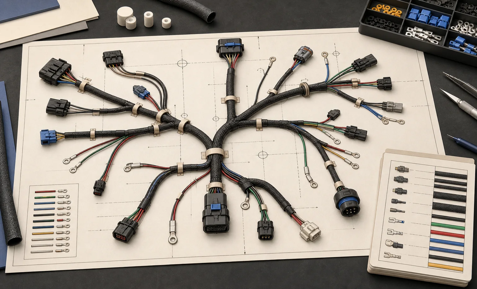

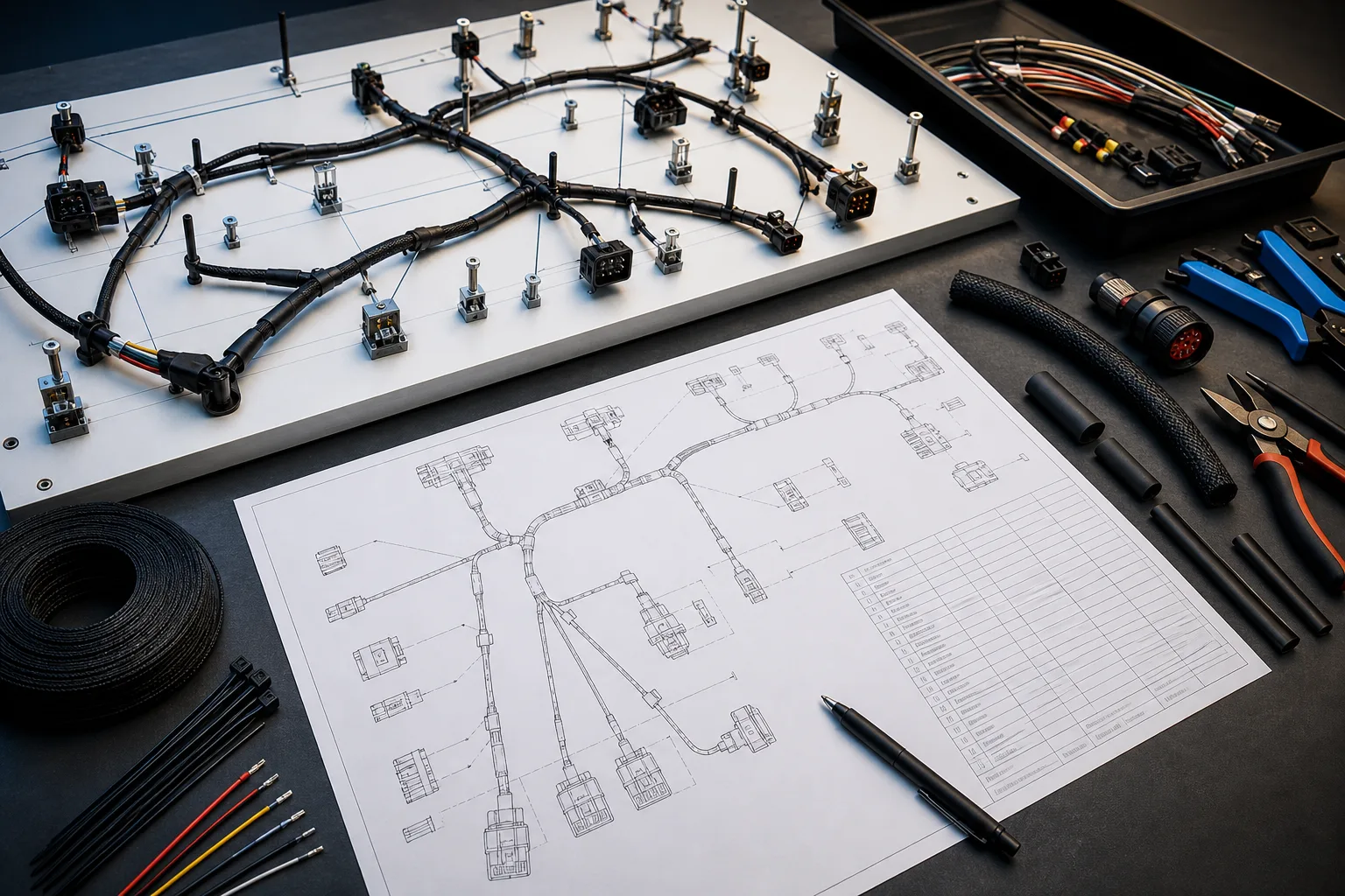
Schematic, connectivity table, and formboard are different views
A wiring schematic explains electrical function. A connectivity table defines exact pin-to-pin relationships. A formboard or nail-board describes physical branch placement and manufacturing dimensions. This workspace starts with an editable 2D drawing and structured connectivity, then derives schedules and route-based cut lengths. It does not pretend that an unscaled sketch is a production formboard.
- Connector and pin endpoints remain explicit
- From-to labels include device tags and terminal identifiers
- Route segments provide a measurable basis for cut-length estimates
- Physical calibration remains the designer’s responsibility
Model the data assembly teams need
Each conductor can carry an identifier, color, gauge or cross-section, material, insulation, signal class, cable and core assignment, length, slack, from/to locations, and end terminations. Devices store manufacturer, catalog, description, installation location, terminal mapping, and custom fields.
- Pin-to-pin wire and cable-core allocation
- Crimp, ferrule, lug, or other end-termination descriptions
- Connector, splice, junction, and inline-device symbols
- Project device library for reusable rated parts
Turn drawing geometry into a controlled cut list
The harness helper totals the routed segment length for every wire and applies its stored slack percentage—or a default value when none is entered. Existing cable and core identifiers are preserved. The generated data remains editable and appears immediately in wire, cable, and label schedules.
- Per-wire route length and slack
- Automatic core numbering for missing values
- Cable conductor-count checks
- CSV output for downstream cutting and labeling workflows
Use generic or custom connector and termination records
Connector bodies, terminal blocks, plugs, headers, splices, lugs, and inline devices can begin as generic library objects or custom project devices. A custom profile can record its dimensions, pin roles, terminal labels, manufacturer, catalog number, and notes. Exact supplier compatibility still depends on the source datasheet and the designer’s cavity, crimp, seal, and mating-part review.
- Editable pin and terminal identifiers
- Manufacturer and catalog fields stay attached to the drawing object
- Project library records support reuse without changing global symbols
- Starter profiles remain visibly separate from manufacturer-certified CAD
Check connectivity before creating build reports
From-to schedules are only useful when both endpoints are real. Wires snap to registered pins, and the document checks can expose orphan conductors, duplicate identifiers, missing conductor data, or inconsistent cable-core allocation. Reviewers can open the affected object directly, correct it, and regenerate the schedule from the same source model.
- Registered pin endpoints rather than free-floating line ends
- Duplicate wire-number and missing-size checks
- Cable conductor-count and core-usage checks
- Review findings remain distinct from certified production validation
Document labels and splices, not just wires
General drawing tools stop at lines. The engineering reports now include device labels, wire markers, terminal labels, and a splice schedule derived from junction/splice devices and their connected conductors. These reports make hidden assembly details visible during review and can be exported independently.
- Device-tag and description labels
- Wire number, from, to, color, and gauge markers
- Terminal strip and terminal-number labels
- Splice tag, connected conductor count, and wire-number list
Bring existing engineering data without flattening the drawing
Harness work often starts in spreadsheets. The CSV importer deliberately separates structured data from geometry: device rows match existing drawing objects by tag, while cable and terminal rows append validated records. This avoids turning a spreadsheet into an unreviewable picture and prevents formulas or macros from executing in the browser.
- UTF-8 CSV with an explicit header row
- Device properties matched by stable tag
- Cable conductor count, type, gauge, length, locations, and notes
- Terminal strip, number, function, device, pin, level, and location
Control change through review and release
A manufacturing package is only useful if the team can identify what changed. Project members can comment on anchored drawing objects, assign review actions, compare object-level revisions, restore a prior version, and issue a sequential immutable release. Exported project JSON provides a versioned portability format alongside printable and tabular deliverables.
- Owner, administrator, editor, and viewer roles
- Assigned open and resolved review comments
- Added, removed, and modified object comparison
- Content-addressed release snapshots for handoff
Choose the right tool boundary
This workflow fits documentation-sized harnesses, control cabinets, prototypes, machinery, audio, robotics, trailers, and service wiring where browser access and synchronized schedules matter. Choose dedicated enterprise harness software when the project requires bidirectional ECAD/MCAD exchange, automated 3D routing, connector-cavity validation against a supplier database, 1:1 nail-board dimensioning, or production-machine integration.
- Useful for concept-to-assembly documentation
- Strongest when the drawing is the source for schedules
- Not a substitute for 3D packaging and bend-radius simulation
- Explicit limitations reduce false confidence at handoff
Workflow
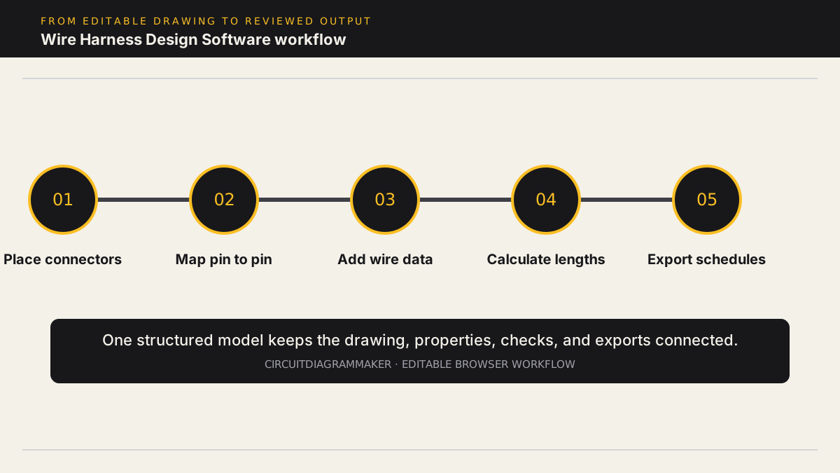
- Place connectors, plugs, headers, terminals, splices, protection, and inline devices, then draw pin-to-pin connections.
- Record wire number, gauge or cross-section, color, insulation, cable/core, signal class, termination, and location data.
- Calculate route length from drawing segments, add per-wire slack, and organize conductors into a generated harness cable.
- Generate from-to, cut-list, cable, terminal, label, splice, device, and connector-ready schedules and check core usage.
- Import existing device, cable, or terminal CSV data and export the reviewed drawing package for assembly handoff.
Deliverables
- From-to wire list: Pin endpoints, wire number, color, gauge, cable/core, length, slack result, and terminations.
- Harness cut list: Route-derived conductor lengths with per-wire slack and generated cable/core assignments.
- Label and splice schedules: Device labels, wire markers, terminal markers, splice tags, and connected conductors.
- Assembly package: Drawing exports, device/BOM, cable and terminal schedules, project JSON, review comments, and releases.
Current limitations
- The current workflow is 2D and does not exchange MCAD geometry or automatically route a harness through a 3D assembly.
- A route-derived length is only as accurate as the drawing scale and path; calibrate it before using a cut list for production.
- Automated 1:1 nail-board dimensions, bend-radius simulation, supplier cavity libraries, and production-machine output are not shipped.
Capability sources
- Product capability matrix
- Simulation model compatibility
- Physical component library and verification states
Related electrical design workflows
Frequently asked questions
What should wire harness design software produce?
At minimum: an understandable drawing, exact pin-to-pin connectivity, a bill of materials, wire and cable lists, cut lengths, terminal or connector information, labels, and revision-controlled handoff files.
Can I import harness data from Excel or CSV?
The Engineering workspace imports UTF-8 CSV for device properties, cable schedules, and terminal plans. It does not currently interpret arbitrary Excel workbooks or automatically infer an entire harness from unstructured sheets.
Does it create a 1:1 formboard?
Not automatically. The editor provides a 2D routed drawing and route-derived length estimates. Production formboard dimensions and drawing-scale calibration still need explicit engineering control.
Can it document splices and connector pins?
Yes. Junction or splice devices can be connected in the drawing, endpoints retain pin identifiers, and live reports expose splice connectivity, wires, terminals, labels, cable cores, and from-to data.
Open a PLC wiring sample or review the capability matrix.