Direct-On-Line (DOL) Motor Starter Circuit Diagram
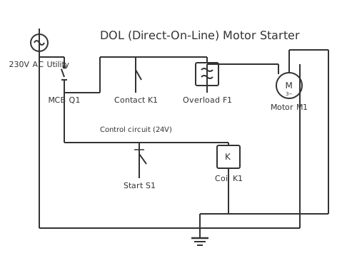
This is a free printable dol wiring diagram: download the diagram as SVG or open it and print to paper or PDF.
Direct-on-line (DOL) motor starters provide simple on-off control for three-phase motors through electromagnetic contactors.
Diagram checks and scope
- Components
- 8
- Wired connections
- 10
- Automated check
- Automated pin, route, source, and topology checks passed; this is not a safety certification.
Direct-on-line (DOL) motor starting applies full three-phase voltage directly to motor terminals, enabling instant torque development. The DOL circuit uses three main components: a magnetic contactor (relay) switching high-current connections, an overload relay providing motor protection, and a control circuit energizing the contactor. A pushbutton control station contains a Start button energizing the contactor coil. Energizing the contactor pulls an armature that closes three heavy-duty power contacts, simultaneously supplying all three phases to the motor windings. The contactor includes a held-in circuit maintaining coil energization after the Start button is released. A Stop button de-energizes the contactor. The overload relay monitors motor current continuously—if current exceeds the setpoint (typically 125% of motor full-load current), the relay trips, de-energizing the contactor. This protection prevents motor overheating from jamming, low voltage, or phase loss. The control circuit operates at reduced voltage (120V) independent of the three-phase power level.
How to wire dol wiring diagram
- Identify the motor full-load current from the motor nameplate
- Select a contactor rated for at least this current with 25% safety margin
- Mount the contactor and overload relay in a control enclosure with proper spacing
- Wire the three-phase input to the contactor main contacts
- Connect the motor terminals to the contactor output
Frequently asked questions
What is the difference between DOL starting and soft-starting?
DOL starting applies full voltage instantly, producing high inrush current (6-10x normal). Soft-starting gradually ramps voltage, reducing inrush to 2-3x normal.
How does the overload relay protect the motor?
The overload relay monitors motor current and compares it to a setpoint. If current exceeds the setpoint, the relay trips after a few seconds.
What voltage should the DOL control circuit use?
Most DOL control circuits operate at 120V AC, derived from a control transformer stepping down the main three-phase voltage.
Can I manually reset an overload relay after it trips?
Yes. Once the motor overload condition is removed, press the manual reset button to restore normal operation.
What size contactor should I select for a three-phase motor?
Select a contactor rated for at least the motor full-load current at the required voltage, with 25% safety margin.
Sources and verification
Review status: Not independently reviewed. Automated topology checks confirm stored terminals and routes, not the correctness of manufacturer pin assignments, ratings, regional codes, or installation decisions. Verify those claims against the current primary documentation before use.
- IEC 61082-1:2014 — Rules for electrotechnical documents — International Electrotechnical Commission. Supports: General diagram, drawing, table, and reference-designation presentation conventions. Checked 2026-07-15.
Related diagrams
- 3 phase dol starter wiring diagram
- dol circuit diagram
- dol control diagram
- dol power diagram
- dol starter circuit diagram
- dol starter control circuit