Wire Gauge Chart: AWG, mm², Diameter and Ampacity
AWG identifies conductor geometry; it does not determine ampacity by itself. Use this chart for size comparison, then check the complete installation and code conditions.
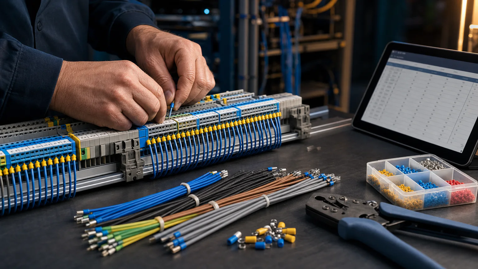


AWG wire size, diameter, area, and copper ampacity chart
AWG is a geometric size system, not an amp rating. The diameter and area columns describe a solid round conductor. The ampacity columns are planning references based on NEC Table 310.16 conditions; the usable ampacity depends on conductor material, insulation, terminal rating, ambient temperature, conductor count, cable or raceway, installation method, small-conductor limits, and the locally adopted code.
| AWG | Solid diameter (mm) | Area (mm²) | Circular mils | Cu 60 °C (A) | Cu 75 °C (A) | Cu 90 °C (A) |
|---|---|---|---|---|---|---|
| 14 | 1.628 | 2.081 | 4,110 | 15 | 20 | 25 |
| 12 | 2.053 | 3.309 | 6,530 | 20 | 25 | 30 |
| 10 | 2.588 | 5.261 | 10,380 | 30 | 35 | 40 |
| 8 | 3.264 | 8.367 | 16,510 | 40 | 50 | 55 |
| 6 | 4.115 | 13.30 | 26,240 | 55 | 65 | 75 |
| 4 | 5.189 | 21.15 | 41,740 | 70 | 85 | 95 |
| 3 | 5.827 | 26.67 | 52,620 | 85 | 100 | 115 |
| 2 | 6.544 | 33.62 | 66,360 | 95 | 115 | 130 |
| 1 | 7.348 | 42.41 | 83,690 | 110 | 130 | 145 |
| 1/0 | 8.251 | 53.49 | 105,600 | 125 | 150 | 170 |
| 2/0 | 9.266 | 67.43 | 133,100 | 145 | 175 | 195 |
| 3/0 | 10.405 | 85.01 | 167,800 | 165 | 200 | 225 |
| 4/0 | 11.684 | 107.2 | 211,600 | 195 | 230 | 260 |
The dimensions align with the AWG geometry standardized by ASTM B258. The listed copper ampacities align with the corresponding NEC Table 310.16 columns for the stated baseline conditions. For 14, 12, and 10 AWG copper, NEC small-conductor protection rules normally cap overcurrent protection at 15, 20, and 30 A even when a higher-temperature table column shows a larger value.
Quick AWG to mm² equivalents
AWG and IEC metric conductor sizes are separate standard series, so conversion is approximate. Select the next suitable standard metric size after checking current capacity, voltage drop, temperature, grouping, installation method, terminal range, and manufacturer data.
| AWG area | Nearest common metric size | Important note |
|---|---|---|
| 14 AWG = 2.08 mm² | 2.5 mm² | Do not infer equal ampacity from area alone. |
| 12 AWG = 3.31 mm² | 4 mm² | Terminal and wiring-method rules still govern. |
| 10 AWG = 5.26 mm² | 6 mm² | Check the actual metric cable table. |
| 8 AWG = 8.37 mm² | 10 mm² | Round upward for area comparison. |
| 6 AWG = 13.30 mm² | 16 mm² | Verify lug and gland range. |
| 4 AWG = 21.15 mm² | 25 mm² | Installation method can dominate current capacity. |
| 2 AWG = 33.62 mm² | 35 mm² | Voltage drop may require a larger size. |
| 1/0 AWG = 53.49 mm² | 70 mm² | 50 mm² is smaller; 70 mm² is the next listed size. |
How to choose a wire size correctly
- Establish design current. Use the applicable load, continuous-duty, motor, transformer, demand, diversity, and protective-device rules.
- Select the governing wiring standard and installation method. A conductor in free air, cable, conduit, tray, insulation, soil, or a bundle has different thermal conditions.
- Apply terminal-temperature and small-conductor limits. A 90 °C insulation marking does not automatically allow the final circuit to use the 90 °C ampacity column.
- Apply ambient and grouping correction. More current-carrying conductors and higher ambient temperature normally reduce allowable current.
- Check voltage drop. Long runs can require a larger conductor even after the thermal requirement is satisfied.
- Check short-circuit withstand and protection. The protective device, fault level, clearing time and conductor must be coordinated.
- Verify physical compatibility. Confirm insulation type, conductor class, bend radius, conduit fill, lug range, gland, termination method, environment and regional approval.
Diameter is not finished cable diameter
The diameter in an AWG chart is the nominal diameter of a solid round conductor. A stranded conductor has the same nominal conductive area but a different overall bundle diameter. Insulation, jacket, shielding, armor and filler increase the finished cable diameter again. Use the cable manufacturer’s published outside diameter for conduit fill, bend radius, glands, connectors and routing space.
Copper versus aluminum
Aluminum needs a larger cross-sectional area than copper for a comparable current and voltage-drop result. It also requires equipment listed for aluminum, appropriate surface preparation and termination practice, and the torque specified by the equipment manufacturer. Never substitute by AWG number alone.
Primary references and review state
- ASTM B258 — standard nominal AWG diameters and cross-sectional areas.
- NFPA LiNK — available NFPA 70 editions. Confirm the edition adopted by the authority having jurisdiction.
- IEC 60287-1-1:2023 — cable current-rating equations and loss calculation context.
This chart was reviewed on 2026-07-30. It is an educational planning reference, not an installation instruction or substitute for the complete adopted standard.
Frequently asked questions
What size is 12 AWG in mm²?
12 AWG has a nominal conductive area of about 3.31 mm². The next common IEC size by area is 4 mm², but the two are not interchangeable without checking the applicable current-rating and installation rules.
How many amps can 12 AWG copper carry?
The NEC Table 310.16 baseline columns list 20, 25, and 30 A at 60, 75, and 90 °C, but small-conductor rules normally limit 12 AWG copper to 20 A overcurrent protection. The full installation conditions still apply.
Does a smaller AWG number mean a larger wire?
Yes. AWG diameter and area increase as the gauge number decreases. Sizes larger than 1 AWG continue as 1/0, 2/0, 3/0, and 4/0.
Can I use conductor diameter for conduit fill?
No. Use the finished insulated conductor or cable area published for the exact type. Bare solid-conductor diameter omits insulation, strand lay, jacket and other construction layers.
Is 10 AWG the same as 6 mm²?
10 AWG is about 5.26 mm², so 6 mm² is the nearest larger common metric size. Electrical ratings still depend on the governing standard and installation method.
Related tools & references
Last verified: 2026-07-30