Control Panel Wiring Templates
Quick answer: A control-panel template should be a structured project rather than a flat image. Tags, wires, terminals, parts and physical placement need to remain editable and traceable.
User job: Accelerate a panel documentation project without hiding engineering decisions.
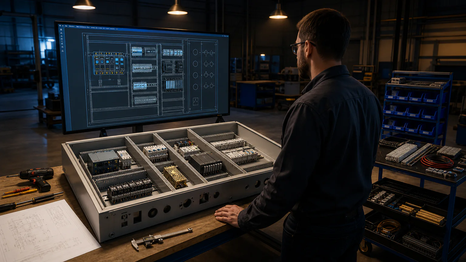


Worked example
Start from a motor or PLC template, add exact devices, generate the BOM and terminal plan, then arrange the backplate and door in the panel workspace.
Step-by-step workflow
- Choose the closest functional starter
- Adapt the schematic
- Attach part and terminal data
- Generate schedules
- Review 2D/3D layout and release
Outputs and deliverables
- Editable schematic starter
- BOM and terminal data
- Panel placement baseline
- Review checklist
- Export package
Working editable starters
- DOL Motor Starter — Open an editable direct-on-line motor starter template with start/stop control, contactor seal-in, overload protection, and a running indicator.
- Star-Delta Motor Starter — Edit a star-delta starter template with main, star, and delta contactors, timed changeover, overload protection, and interlocking.
- Forward-Reverse Motor Control — Start with an editable reversing motor circuit containing forward and reverse contactors, seal-in contacts, overload protection, and interlocks.
- Lighting Panel Circuit — Edit a multi-circuit lighting panel template with incoming supply, branch protection, switches, luminaires, neutral, and protective conductors.
- PLC Input/Output Wiring — Edit a PLC I/O wiring template with a 24 VDC supply, field pushbuttons, digital inputs, digital outputs, and pilot lights.
Quality checks before issue
- All generic parts are reviewed
- Panel and schematic tags agree
- Door/backplate placement is correct
- Clearance and heat are assessed externally
- The release identifies the project state
Current product and engineering boundaries
- Templates are not pre-certified assemblies.
- Thermal and short-circuit studies are outside scope.
- Manufacturer cutout and spacing data govern construction.
Reviewed 2026-07-30: Product capabilities are first-party facts. Engineering examples are educational and must be verified for the actual project, equipment and jurisdiction.
Frequently asked questions
What is Control Panel Wiring Templates used for?
A control-panel template should be a structured project rather than a flat image. Tags, wires, terminals, parts and physical placement need to remain editable and traceable.
What does this workflow produce?
Editable schematic starter, BOM and terminal data, Panel placement baseline, Review checklist, Export package.
What should be checked before using the result?
All generic parts are reviewed Panel and schematic tags agree Door/backplate placement is correct Clearance and heat are assessed externally The release identifies the project state
What does CircuitDiagramMaker not automate here?
Templates are not pre-certified assemblies. Thermal and short-circuit studies are outside scope. Manufacturer cutout and spacing data govern construction.
Can I continue with an editable project?
Yes. The page links to the closest supported editor, template, calculator, component library, or engineering workspace action.
Open panel design software or inspect the current product capability matrix.