Cable and Wire Schedule Workflow
Quick answer: A cable and wire schedule should be derived from real connected endpoints, not manually retyped from a drawing. Each row needs stable identifiers, from/to locations, terminals, conductor size and color, cable/core assignment, length basis, termination and revision state.
User job: Convert connected drawing data into assembly and installation schedules without spreadsheet drift.
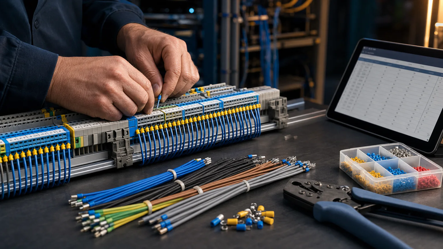


Worked example
For a control panel and remote junction box, map each conductor from device pin to terminal, assign a cable and core, add routing length and slack, then export the reviewed schedule for labeling and assembly.
Step-by-step workflow
- Place devices with stable reference tags
- Connect registered pins and number wires
- Assign cable, core, size, color and termination data
- Check missing endpoints, duplicates and core capacity
- Export wire, cable, label and splice schedules together
Outputs and deliverables
- Wire from-to list
- Cable and core schedule
- Cut-length and slack basis
- Wire and device labels
- Splice and termination schedule
Quality checks before issue
- Every conductor has two valid endpoints
- Identifiers are unique
- Cable core count is not exceeded
- Lengths state their measurement basis
- Exports match the reviewed project version
Current product and engineering boundaries
- Drawing-derived length is only as accurate as route scale and calibration.
- The workflow does not replace 3D harness routing or machine-specific manufacturing output.
- Exact connector cavities and terminations require supplier data.
Reviewed 2026-07-30: Product capabilities are first-party facts. Engineering examples are educational and must be verified for the actual project, equipment and jurisdiction.
Frequently asked questions
What is Cable and Wire Schedule Workflow used for?
A cable and wire schedule should be derived from real connected endpoints, not manually retyped from a drawing. Each row needs stable identifiers, from/to locations, terminals, conductor size and color, cable/core assignment, length basis, termination and revision state.
What does this workflow produce?
Wire from-to list, Cable and core schedule, Cut-length and slack basis, Wire and device labels, Splice and termination schedule.
What should be checked before using the result?
Every conductor has two valid endpoints Identifiers are unique Cable core count is not exceeded Lengths state their measurement basis Exports match the reviewed project version
What does CircuitDiagramMaker not automate here?
Drawing-derived length is only as accurate as route scale and calibration. The workflow does not replace 3D harness routing or machine-specific manufacturing output. Exact connector cavities and terminations require supplier data.
Can I continue with an editable project?
Yes. The page links to the closest supported editor, template, calculator, component library, or engineering workspace action.
Open the harness workflow or inspect the current product capability matrix.