Diode Rectifier Simulator
Quick answer: A rectifier converts alternating polarity into a unidirectional waveform. Load, source frequency, diode behavior and smoothing capacitance determine average output, ripple and peak diode current.
User job: See how rectifier topology and filtering change the output waveform.


Worked example
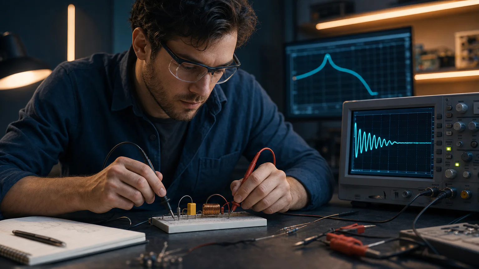
A 50 Hz full-wave bridge produces 100 Hz ripple before filtering. Increasing capacitance reduces nominal ripple but increases charging pulses and inrush.
Step-by-step workflow
- Choose half-wave or bridge topology
- Set source, load and diode assumptions
- Run transient analysis
- Add a smoothing capacitor
- Compare ripple and current stress
Outputs and deliverables
- Editable rectifier circuit
- Input/output waveform comparison
- Ripple-frequency explanation
- Filter sensitivity example
- Real-diode verification list
Quality checks before issue
- Diode orientation is correct
- Peak inverse voltage has margin
- Load and capacitor ratings are credible
- Startup is simulated long enough
- Transformer/source impedance is not ignored
Current product and engineering boundaries
- The result is not a power-supply thermal or safety design.
- Recovery, junction temperature and transformer regulation need part-specific models.
- Mains-connected circuits require qualified design and isolation.
Reviewed 2026-07-30: Product capabilities are first-party facts. Engineering examples are educational and must be verified for the actual project, equipment and jurisdiction.
Frequently asked questions
What is Diode Rectifier Simulator used for?
A rectifier converts alternating polarity into a unidirectional waveform. Load, source frequency, diode behavior and smoothing capacitance determine average output, ripple and peak diode current.
What does this workflow produce?
Editable rectifier circuit, Input/output waveform comparison, Ripple-frequency explanation, Filter sensitivity example, Real-diode verification list.
What should be checked before using the result?
Diode orientation is correct Peak inverse voltage has margin Load and capacitor ratings are credible Startup is simulated long enough Transformer/source impedance is not ignored
What does CircuitDiagramMaker not automate here?
The result is not a power-supply thermal or safety design. Recovery, junction temperature and transformer regulation need part-specific models. Mains-connected circuits require qualified design and isolation.
Can I continue with an editable project?
Yes. The page links to the closest supported editor, template, calculator, component library, or engineering workspace action.
Open a rectifier circuit or inspect the current product capability matrix.