Electrical Panel Builder Software
Quick answer: Panel-builder software creates value when the schematic, schedules, parts, layout, review findings and released package share one source model. That reduces retyping and makes each change traceable.
User job: Move a control-panel project from concept to a documented assembly package.
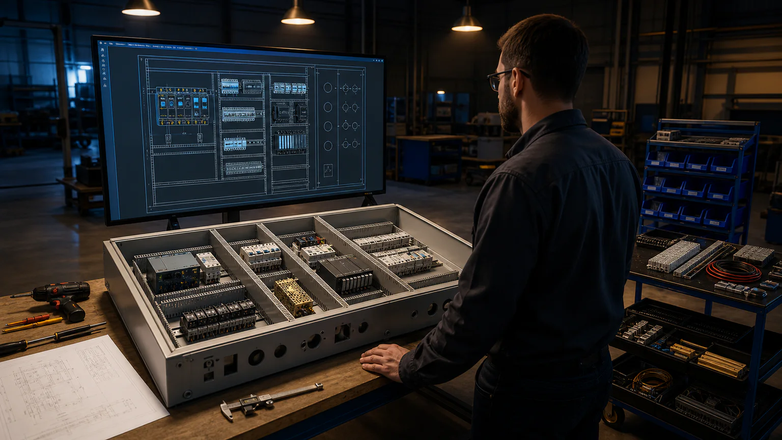


Worked example
A motor-control panel can combine incoming protection, contactors, overloads, PLC I/O, power supply, terminals and operators, then generate synchronized BOM, wire, terminal, label and panel outputs.
Step-by-step workflow
- Build the schematic and tag devices
- Generate wire, PLC and terminal data
- Map exact or generic physical components
- Arrange the 2D panel and inspect 3D fit
- Review, release and export the package
Outputs and deliverables
- Multi-page schematic
- BOM and wire schedules
- Terminal and PLC I/O plans
- 2D/3D panel visualization
- Reviewed release package
Quality checks before issue
- Every placed physical part traces to design intent
- Panel collisions and outside placements are resolved
- Part ratings and heat are engineered separately
- Door and backplate devices use correct surfaces
- Released outputs share one version
Current product and engineering boundaries
- The 3D workspace is visualization, not MCAD.
- Thermal, fault, coordination and machining studies are not automated.
- STEP/Parasolid editing and certified manufacturer CAD are not included.
Reviewed 2026-07-30: Product capabilities are first-party facts. Engineering examples are educational and must be verified for the actual project, equipment and jurisdiction.
Frequently asked questions
What is Electrical Panel Builder Software used for?
Panel-builder software creates value when the schematic, schedules, parts, layout, review findings and released package share one source model. That reduces retyping and makes each change traceable.
What does this workflow produce?
Multi-page schematic, BOM and wire schedules, Terminal and PLC I/O plans, 2D/3D panel visualization, Reviewed release package.
What should be checked before using the result?
Every placed physical part traces to design intent Panel collisions and outside placements are resolved Part ratings and heat are engineered separately Door and backplate devices use correct surfaces Released outputs share one version
What does CircuitDiagramMaker not automate here?
The 3D workspace is visualization, not MCAD. Thermal, fault, coordination and machining studies are not automated. STEP/Parasolid editing and certified manufacturer CAD are not included.
Can I continue with an editable project?
Yes. The page links to the closest supported editor, template, calculator, component library, or engineering workspace action.
See the panel workflow or inspect the current product capability matrix.