Magnetic Contactor Wiring & Three-Phase Motor Control
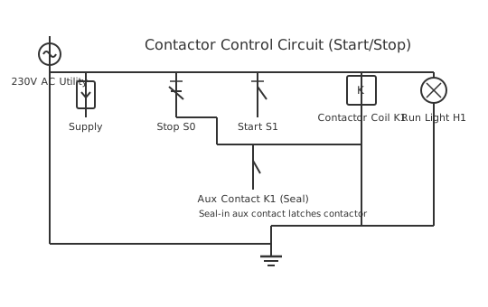
This is a free printable magnetic contactor wiring diagram: download the diagram as SVG or open it and print to paper or PDF.
Magnetic contactors are electromagnetically-actuated switches used to control three-phase motors in industrial applications.
Diagram checks and scope
- Components
- 8
- Wired connections
- 10
- Automated check
- Automated pin, route, source, and topology checks passed; this is not a safety certification.
A magnetic contactor is an industrial-grade relay designed for switching high-power three-phase AC circuits. The typical contactor contains a movable armature attracted to an electromagnet when the coil is energized. Three primary power contacts switch the three-phase input lines to motor terminals. When the control coil receives power (typically 24V AC or 120V AC), the electromagnet pulls the armature, closing all contacts simultaneously. Contactors rated for 30-600 amps at three-phase voltages are common in industrial settings. The electromagnetic coil is wound for control voltage operation. Arc suppression features separate and cool arcs created when high-current circuits are broken. Some contactors include auxiliary contacts providing feedback signals indicating contactor state. Overload relay blocks mounted to contactor terminals provide integrated thermal or electronic overload protection. Contactor life spans millions of electrical cycles when properly applied.
How to wire magnetic contactor wiring diagram
- Turn off and lock out all power sources before working on three-phase systems
- Verify contactor coil voltage matches your control system voltage
- Connect three-phase input lines to contactor terminals using properly sized cable
- Connect motor leads to contactor output terminals matching motor nameplate voltage
- Connect control voltage to contactor coil through start and stop button circuits
- Test by pressing start button and verifying motor receives power
Frequently asked questions
What is the difference between a contactor and a relay?
Contactors are heavy-duty relays rated for continuous full-load current in industrial applications.
What voltage for the coil?
Standard voltages are 24V AC, 120V AC, or 480V AC depending on the control system design.
How do I verify it works?
Deactivate the motor and apply control voltage, listening for a mechanical clicking sound.
What causes early failure?
Short circuits, excessive inrush currents, and insufficient cooling accelerate contactor wear.
Can I control it remotely?
Yes, this is a primary advantage - run control wiring to the contactor coil from remote switches.
Sources and verification
Review status: Not independently reviewed. Automated topology checks confirm stored terminals and routes, not the correctness of manufacturer pin assignments, ratings, regional codes, or installation decisions. Verify those claims against the current primary documentation before use.
- IEC 61082-1:2014 — Rules for electrotechnical documents — International Electrotechnical Commission. Supports: General diagram, drawing, table, and reference-designation presentation conventions. Checked 2026-07-15.
Related diagrams
- hager contactor wiring diagram
- 2 pole contactor wiring diagram
- 220v contactor wiring diagram
- 240 volt contactor wiring diagram
- 3 phase contactor wiring diagram
- 3 phase contactor wiring diagram a1 a2