Proper Motor Terminal Identification and Wiring
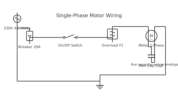
This is a free printable motor connection diagram: download the diagram as SVG or open it and print to paper or PDF.
A motor connection diagram shows correct terminal identification for connecting three phase and single phase motors to power supplies.
Diagram checks and scope
- Components
- 7
- Wired connections
- 8
- Automated check
- Automated pin, route, source, and topology checks passed; this is not a safety certification.
Motor terminals are labeled according to NEMA standards that identify winding connections and proper phase sequence. Three phase motors typically have six terminals for dual-voltage operation: three for delta (low voltage) and three for star (high voltage) configuration. Terminal designations T1, T2, T3 represent the three phase inputs for delta connection, while additional terminals T4-T6 enable star wiring. Some motors use simpler three-terminal configurations for fixed delta or star operation. Single phase motors require separate identification of running and starting windings. Correct terminal connection is essential for proper motor operation and rotation direction. Incorrect phasing causes the motor to run backward or not start at all. The motor nameplate includes a wiring diagram showing the correct connection for your specific voltage and operation. Overloaded motors may develop unequal phase currents indicating improper wiring. Testing with a multimeter between terminals verifies proper continuity of windings before applying power. Phase rotation checkers verify correct three phase sequence after wiring is complete.
How to wire motor connection diagram
- Locate the motor nameplate and read the wiring diagram carefully
- Identify the terminal block and examine terminal identification labels
- Follow the wiring diagram path, connecting supply leads to the correct terminals
- Use the same gauge wire for all connections to ensure balanced current distribution
- Test continuity between correct terminal pairs before applying power
Frequently asked questions
What do motor terminal letters mean?
Standard NEMA designation: T1-T3 for three phase or main windings, T4-T6 for alternate configurations.
Can I change a three phase motor to single phase?
No, three phase and single phase motors use different winding designs and require different circuits.
How do I know which terminals to use?
Check the motor nameplate for a wiring diagram matching your desired voltage and operation.
What happens if I connect the terminals incorrectly?
Motor may not start, run backward, overheat, or draw excessive current, risking damage.
How do I identify high voltage versus low voltage terminals?
Motors are labeled, usually with separate terminal groups or distinct markings for each voltage option.
Sources and verification
Review status: Not independently reviewed. Automated topology checks confirm stored terminals and routes, not the correctness of manufacturer pin assignments, ratings, regional codes, or installation decisions. Verify those claims against the current primary documentation before use.
- IEC 61082-1:2014 — Rules for electrotechnical documents — International Electrotechnical Commission. Supports: General diagram, drawing, table, and reference-designation presentation conventions. Checked 2026-07-15.
Related diagrams
- 4 wire stepper motor wiring diagram
- servo motor circuit diagram
- servo motor pin diagram
- servo motor wiring diagram
- stepper motor circuit diagram
- stepper motor pinout