one way switch diagram
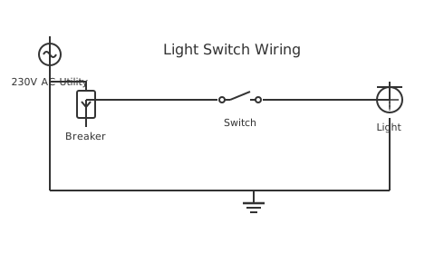
This is a free printable one way switch diagram: download the diagram as SVG or open it and print to paper or PDF.
Diagram checks and scope
- Components
- 5
- Wired connections
- 5
- Automated check
- Automated pin, route, source, and topology checks passed; this is not a safety certification.
A one-way switch diagram shows the electrical circuit for controlling a single light or fixture from one switch location, representing the simplest form of lighting control. The diagram illustrates how the switch interrupts the hot wire between the power source and the light fixture, allowing current flow only when the switch contacts close. One-way switches have two terminals: one for incoming hot wire (line) and one for outgoing wire to the fixture (load). The neutral and ground wires bypass the switch entirely, providing return paths and safety grounding respectively. This diagram is fundamental for understanding residential lighting installation, serving as the foundation for more complex multi-location switch arrangements. Proper wire color coding is essential: black or red for hot, white for neutral, and green or bare copper for ground conductors. Understanding one-way switch operation enables homeowners and electricians to troubleshoot non-functional lights and safely perform basic electrical work.
How to wire one way switch diagram
- Identify the switch loop cable A one-way switch is wired in a loop: live from the supply goes down to the switch, switched live returns up to the lamp, and neutral goes directly to the lamp without passing through the switch. Confirm which wire is which before connecting.
- Prepare the wall box Fit the wall box flush with the plaster surface. A surface-mounted box that sticks out from the wall causes the switch plate to flex when pressed — this stresses the terminal connections over time.
- Connect live to switch input Connect the permanent live (incoming) to the common or line terminal of the switch. In most SA switches this is the upper terminal. Tighten the screw firmly.
- Connect switched live from switch output Connect the outgoing switched live to the output terminal of the switch. This conductor carries current only when the switch is closed. Sleeve this conductor brown if it is not already brown.
- Fit earth if required Metal switch plates require an earth connection. Connect the earth conductor to the earth lug on the metal plate or the earth terminal in the box. Plastic switch plates are class II — earth is not required at the switch body but run it to the box anyway.
- Test with a multimeter or continuity tester Before closing the wall box, use a continuity tester to verify the switch works — continuity in on position, open circuit in off position. Fitting the plate and energising a wired-backwards switch is an avoidable waste of time.
Frequently asked questions
What is a one-way switch and how does it work?
A one-way (single pole single throw) switch interrupts the live conductor in a circuit. When open, the circuit is broken and no current flows to the load. When closed, current flows through the switch to the load. The neutral is never switched.
Can I wire a light fitting without an earth if I have a plastic switch?
A plastic double-insulated switch does not need an earth connection on the switch body, but the circuit earth conductor must still be run and connected at the light fitting if the fitting has any exposed metal. The earth is for the fitting, not the switch.
Why does my light stay on when the switch is off?
Either the switch is wired across the neutral instead of the live, or there is a back-feed from another circuit sharing the neutral. In both cases the load is partially energised. This is a dangerous condition — do not operate the fitting until the wiring is corrected.
What is the correct switch position for a one-way switch?
In SA convention, the switch should be wired so that the up position is on and down is off. This is a SANS convention for safety — a switch left in the down position after an electrical event looks off but should be off to be safe.
How many lights can I connect to one switch?
As many as the circuit and switch rating allows. A standard 6A switch can handle 6A at 230V — that is 1 380W, equating to around 10 to 15 LED downlights. Verify total wattage and check the circuit MCB is not already at capacity.
Sources and verification
Review status: Not independently reviewed. Automated topology checks confirm stored terminals and routes, not the correctness of manufacturer pin assignments, ratings, regional codes, or installation decisions. Verify those claims against the current primary documentation before use.
- IEC 61082-1:2014 — Rules for electrotechnical documents — International Electrotechnical Commission. Supports: General diagram, drawing, table, and reference-designation presentation conventions. Checked 2026-07-15.
Related diagrams
- eaton 3 way switch diagram
- legrand 3 way switch
- 1 gang 1 way switch wiring diagram
- 1 gang 2 way switch wiring diagram
- 1 way light switch wiring diagram
- 2 gang 1 way switch wiring diagram