How to Install and Wire Selector switch wiring diagram
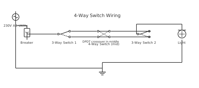
This is a free printable selector switch wiring diagram: download the diagram as SVG or open it and print to paper or PDF.
This comprehensive guide covers proper installation procedures, wiring methodologies, and safety considerations for selector switch wiring diagram systems. Learn correct component selection, circuit configuration, and testing procedures ensuring reliable operation.
Diagram checks and scope
- Components
- 7
- Wired connections
- 9
- Automated check
- Automated pin, route, source, and topology checks passed; this is not a safety certification.
A selector switch provides manual selection between two or more discrete positions or operating modes through rotary or lever actuation. The mechanical design ensures positive engagement in each position with detent mechanisms preventing unintended transitions. Contact architecture enables switching between different circuits or load configurations simultaneously from a single control device. Electrical specifications including voltage and current ratings must accommodate the highest load requirement among all selectable circuits. Watertight enclosure designs protect against moisture intrusion in outdoor applications while maintaining mechanical accessibility for operation. The selector switch mechanism typically features a cam or contact block arrangement that establishes different electrical paths for each selected position. Proper installation requires secure mounting that prevents vibration-induced position changes during operation. Maintenance procedures focus on mechanical lubrication and electrical contact cleaning to ensure reliable position transitions. Application-specific variants include key-selectable switches requiring special keys for safety-critical selections. Integration with automated control systems through position feedback provides monitoring of actual selected state.
How to wire selector switch wiring diagram
- Verify that all power sources are disconnected and locked out before beginning installation work
- Select appropriate mounting location ensuring accessible operator reach and clear view of position indicator
- Install selector switch according to manufacturer specifications using provided mounting hardware
- Connect load circuits to appropriate terminal positions corresponding to each operating mode
- Verify continuity between terminals in each position to confirm proper electrical connectivity
- Test all positions under minimal load conditions before connecting full-power circuits
Frequently asked questions
What is the primary function of a selector switch?
Selector switches allow manual selection between multiple operating modes or circuits from a single control point, enabling flexible circuit configuration without multiple separate switches.
How many positions can a selector switch support?
Standard selector switches typically support 2 to 10 discrete positions, though custom designs can accommodate more. Each position requires dedicated mechanical and electrical components.
What protection mechanisms prevent accidental position changes?
Detent springs and mechanical stops provide positive engagement in each position. Some designs include guarded or shrouded actuators to prevent inadvertent operation.
How should selector switches be maintained?
Regular inspection of mechanical components, light lubrication of pivot points, and occasional electrical contact cleaning maintain reliable operation and extend service life.
What safety considerations apply to selector switch installation?
Ensure proper enclosure rating for environmental conditions, verify load compatibility with electrical ratings, and use appropriate locking mechanisms for safety-critical selections.
Sources and verification
Review status: Not independently reviewed. Automated topology checks confirm stored terminals and routes, not the correctness of manufacturer pin assignments, ratings, regional codes, or installation decisions. Verify those claims against the current primary documentation before use.
- IEC 61082-1:2014 — Rules for electrotechnical documents — International Electrotechnical Commission. Supports: General diagram, drawing, table, and reference-designation presentation conventions. Checked 2026-07-15.
Related diagrams
- auto manual selector switch wiring diagram
- selector switch 2 position wiring diagram
- selector switch 3 position wiring diagram
- 1 wire oil pressure switch wiring diagram
- 2 float switch wiring diagram
- 2 wire oil pressure switch wiring diagram