switch board connection diagram
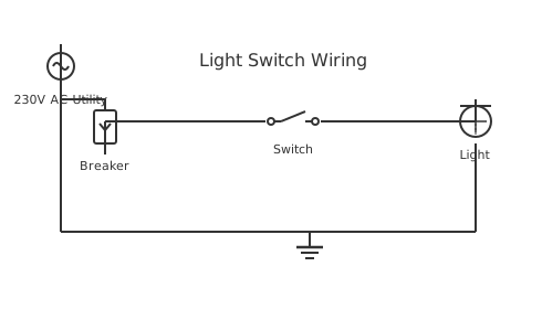
This is a free printable switch board connection diagram: download the diagram as SVG or open it and print to paper or PDF.
Diagram checks and scope
- Components
- 5
- Wired connections
- 5
- Automated check
- Automated pin, route, source, and topology checks passed; this is not a safety certification.
A Switch Board Connection Diagram wiring diagram provides comprehensive guidance for electrical installation and troubleshooting in automotive and industrial applications. This specialized diagram illustrates the proper connections, wire gauges, component placement, and safety procedures required for correct system operation. Understanding this wiring is essential for technicians, electricians, and professionals working with electrical systems. The diagram shows all connections with color coding, amperage ratings, and grounding requirements to ensure safe and reliable operation. Proper installation following this diagram prevents electrical hazards, system failures, and compliance issues. The schematic includes detailed information about terminals, connections, and circuit protection measures. Professional implementation of this diagram ensures optimal system performance, equipment longevity, and electrical safety for all users and equipment.
How to wire switch board connection diagram
- Isolate the main supply before any work Switch off the main incomer MCB or pull the utility fuse. Use a lock-out/tag-out (LOTO) procedure if others have access to the board. Test all busbars with a voltage indicator before touching anything.
- Identify busbar phase assignment and phase colours Per SANS 10142-1, phase conductors are red (L1), yellow/white (L2), blue (L3), and black for neutral. Newer installations follow IEC 60446: brown (L1), black (L2), grey (L3), blue (neutral). Confirm the existing convention before adding circuits.
- Torque busbar connections and MCB terminals Loose busbar connections are a primary cause of switchboard fires in South Africa. Use a calibrated torque screwdriver — MCB terminals are typically 2–4 Nm. Thermal imaging surveys regularly find undertorqued boards.
- Install MCBs with circuit load calculation Each MCB rating must match the minimum cable current rating of its circuit. A 20A MCB protecting 1.5mm² cable (rated 16A) does not protect the cable adequately — size MCBs to the cable, not the connected load.
- Segregate control and power circuits physically If control wiring (relay coils, PLC I/O) shares the board with power circuits, run control cables in separate ducting on a different DIN rail section. Mixed wiring causes induced noise faults and is an inspection failure.
- Complete the circuit schedule before closing the board Label every MCB with circuit description, cable size, and load current. A legible DB schedule is a legal requirement under SANS 10142-1 and is verified during CoC inspection.
- Commission with an insulation resistance test Before energising, test insulation resistance between each phase and earth, and between phases, using a 500VDC Megger. Results below 1MΩ indicate damaged insulation that must be found and repaired before power is applied.
Frequently asked questions
What is a switchboard connection diagram?
A switchboard connection diagram shows how all components within a switchboard are wired together — busbars, circuit breakers, contactors, metering, and outgoing feeders — along with wire numbers, terminal references, and cable sizes. It is the working document used to build and commission the board.
What is the difference between a switchboard and a distribution board?
A distribution board (DB) is a small panel typically feeding final circuits in a domestic or commercial premises. A switchboard is a larger assembly, often in an industrial or commercial context, that may include metering, power factor correction, motor starters, and multiple outgoing distribution feeders.
What busbar sizing do I need for a 400-amp switchboard?
A 400A switchboard typically uses 25mm × 6mm or 30mm × 5mm copper busbars for phase conductors. The exact sizing depends on the continuous current, ambient temperature, and ventilation. Always confirm busbar current-carrying capacity against the manufacturer's derating tables.
Does a switchboard need protection against arc flash?
Yes. SANS 60079 and the OHS Act require arc flash risk assessments for switchboards above 1000V. For low-voltage switchboards, proper protective device coordination, labelled arc flash hazard warnings, and appropriate PPE requirements are mandatory for any person working on live equipment.
Who can certify a new switchboard installation in South Africa?
Switchboard installations must be designed, built, and certified by a registered Wireman or a registered Electrical Engineer, depending on the installation's kVA rating. A Certificate of Compliance is required before energisation, and the installation must comply with SANS 60439 and SANS 10142-1.
Sources and verification
Review status: Not independently reviewed. Automated topology checks confirm stored terminals and routes, not the correctness of manufacturer pin assignments, ratings, regional codes, or installation decisions. Verify those claims against the current primary documentation before use.
- IEC 61082-1:2014 — Rules for electrotechnical documents — International Electrotechnical Commission. Supports: General diagram, drawing, table, and reference-designation presentation conventions. Checked 2026-07-15.
Related diagrams
- 4 switch board connection
- board 2 switch 2 socket connection diagram
- electric switch board wiring diagram
- 1 wire oil pressure switch wiring diagram
- 2 float switch wiring diagram
- 2 wire oil pressure switch wiring diagram