3 phase motor diagram
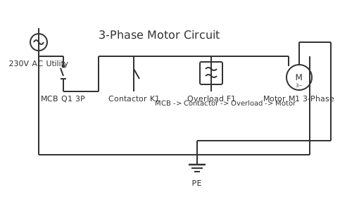
This is a free printable 3 phase motor diagram: download the diagram as SVG or open it and print to paper or PDF.
Diagram checks and scope
- Components
- 6
- Wired connections
- 7
- Automated check
- Automated pin, route, source, and topology checks passed; this is not a safety certification.
A 3 Phase Motor Diagram wiring diagram provides comprehensive guidance for electrical installation and troubleshooting in automotive and industrial applications. This specialized diagram illustrates the proper connections, wire gauges, component placement, and safety procedures required for correct system operation. Understanding this wiring is essential for technicians, electricians, and professionals working with electrical systems. The diagram shows all connections with color coding, amperage ratings, and grounding requirements to ensure safe and reliable operation. Proper installation following this diagram prevents electrical hazards, system failures, and compliance issues. The schematic includes detailed information about terminals, connections, and circuit protection measures. Professional implementation of this diagram ensures optimal system performance, equipment longevity, and electrical safety for all users and equipment.
How to wire 3 phase motor diagram
- Read the motor nameplate for all parameters Record supply voltage (e.g. 380V/660V), connection (delta/star), full-load current (FLC), power factor, speed (RPM), and insulation class from the nameplate. Every downstream component selection depends on these values.
- Open the motor terminal box and identify the six terminals A standard 3-phase induction motor has six winding terminals: U1, V1, W1 (winding starts) and U2, V2, W2 (winding ends). The connection method — star or delta — determines how these are linked and which supply voltage is applied.
- Configure star connection for high-voltage supply Star (Y) connection: U2, V2, and W2 are joined together (the star point), and supply phases L1, L2, L3 connect to U1, V1, W1 respectively. Use star when the supply voltage matches the motor's star voltage rating (typically 380V in SA).
- Configure delta connection for lower voltage supply Delta (Δ) connection: U1-W2, V1-U2, W1-V2 are linked with connecting bars. Supply phases connect to each junction point. Use delta when the supply voltage matches the motor's delta voltage rating (typically 220V for a dual-voltage motor).
- Connect supply conductors and earth at the terminal box Use cable lugs crimped onto the supply conductors. Torque all terminals to the manufacturer's specification — loose motor terminals generate heat and arc tracking that destroys the terminal box insulation over time.
- Earth the motor frame to the protective earth conductor The motor frame earth terminal (marked with the protective earth symbol) connects to the earth conductor in the supply cable. This provides fault protection — a live frame with no earth creates an undetected shock hazard.
- Measure insulation resistance before first start Test with a 500VDC Megger between each winding and earth, and between windings. New motors: above 10MΩ at 500VDC. Used motors: above 1MΩ minimum per IEC 60034-1. Below this threshold, the motor winding insulation is damaged — do not run.
Frequently asked questions
What are the six terminal markings on a three-phase motor terminal block?
A three-phase motor has six winding terminals: U1 and U2 (first winding), V1 and V2 (second winding), W1 and W2 (third winding). These are connected in star (U1-V1-W1 to supply, U2-V2-W2 linked together) or delta (U1 to W2, V1 to U2, W1 to V2) using link bars in the terminal box.
How do I change a three-phase motor from star to delta connection?
Remove the three star links from the terminal block. Fit three delta links connecting U1 to W2, V1 to U2, and W1 to V2. The motor supply cables connect to U1, V1, and W1 (or the linked pairs) as before. Always verify the motor's nameplate confirms both voltage ratings before changing the connection.
What does kW mean on a motor nameplate and how does it relate to amps?
kW is the motor's rated mechanical output power. To estimate running current: I = kW ÷ (√3 × V × power factor × efficiency). For a 5.5kW, 400V, 0.85 PF, 0.92 efficiency motor: I ≈ 5500 ÷ (1.732 × 400 × 0.85 × 0.92) ≈ 10.2A. Always set the overload relay to the nameplate current, not the calculated value.
What does the IP rating on a motor mean?
The IP (Ingress Protection) rating describes protection against solid particles and water. IP54 means protected against dust ingress and splashing water from any direction — suitable for outdoor and wash-down areas. IP65 means dust-tight and jet-wash resistant. IP rating must match the installation environment.
Does a three-phase motor need a neutral connection?
No. A three-phase motor runs on three phase conductors only — no neutral is required. Current flows between the three phases through the motor windings. The motor must still have an earth connection from the terminal box to the installation earth for fault protection.
Sources and verification
Review status: Not independently reviewed. Automated topology checks confirm stored terminals and routes, not the correctness of manufacturer pin assignments, ratings, regional codes, or installation decisions. Verify those claims against the current primary documentation before use.
- IEC 61082-1:2014 — Rules for electrotechnical documents — International Electrotechnical Commission. Supports: General diagram, drawing, table, and reference-designation presentation conventions. Checked 2026-07-15.
Related diagrams
- 230v 3 phase motor wiring diagram
- 3 phase forward reverse motor control circuit diagram
- 3 phase induction motor diagram
- 3 phase motor starter connection
- 3 phase motor to single phase wiring diagram
- 3 phase motor winding diagram