How to Properly Wire Latching Relay Wiring Diagram
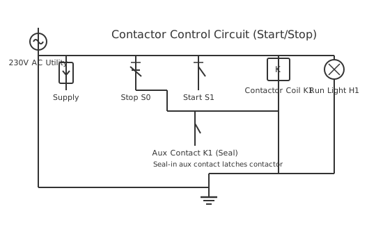
This is a free printable latching relay wiring diagram: download the diagram as SVG or open it and print to paper or PDF.
Understanding proper latching relay wiring diagram connections is critical for electrical safety and system performance. This comprehensive guide walks through each step of the installation process.
Diagram checks and scope
- Components
- 8
- Wired connections
- 10
- Automated check
- Automated pin, route, source, and topology checks passed; this is not a safety certification.
The latching relay wiring diagram is a critical component for safe electrical operation in Self-holding relay circuit configuration. This configuration ensures proper electrical operation through standardized connections and rigorous safety protocols. The diagram illustrates the complete circuit path from power source through components to ground. Understanding this wiring is essential for installation technicians and maintenance personnel. Each component has specific pin configurations that must be followed precisely to avoid equipment damage or safety hazards. The connections shown follow industry standards and best practices for reliability and longevity. Proper installation requires understanding voltage requirements, current ratings, and component compatibility.
How to wire latching relay wiring diagram
- Review the complete latching relay wiring diagram diagram and identify all components and connection points before starting work.
- Turn off power at the main breaker and use a non-contact voltage tester to verify all power is off before beginning installation.
- Prepare wire runs by measuring distances and selecting appropriate gauge and type for your application (copper, stranded, color-coded).
- Install components in their designated locations following the schematic layout, ensuring proper mounting and accessibility for maintenance.
- Make connections following the diagram precisely, testing continuity before restoring power. Perform final operational verification with power on.
Frequently asked questions
What is the main purpose of latching relay wiring diagram?
To safely and reliably connect electrical or control components while preventing overcurrent, short circuits, and shock hazards through proper grounding and circuit protection.
What voltage is required for this latching relay wiring diagram?
This depends on the application: 12-24VDC for automotive and low-voltage circuits, or 120-240VAC for residential and industrial applications. Always verify manufacturer specifications.
How critical is proper grounding in this setup?
Grounding is essential for safety. It provides a low-impedance path for fault currents and prevents dangerous voltages from appearing on equipment enclosures.
What wire gauge should I use?
Wire gauge depends on current requirements and distance: 14AWG for 15A circuits, 12AWG for 20A circuits, and 10AWG for higher amperage. Check local electrical codes.
What tools are needed to install this latching relay wiring diagram?
Basic tools include wire strippers, crimpers, a multimeter for testing, a non-contact voltage tester for safety verification, and appropriate screwdrivers for terminal connections.
Sources and verification
Review status: Not independently reviewed. Automated topology checks confirm stored terminals and routes, not the correctness of manufacturer pin assignments, ratings, regional codes, or installation decisions. Verify those claims against the current primary documentation before use.
- IEC 61082-1:2014 — Rules for electrotechnical documents — International Electrotechnical Commission. Supports: General diagram, drawing, table, and reference-designation presentation conventions. Checked 2026-07-15.
Related diagrams
- 12v latching relay wiring diagram
- 12v 5 pin relay wiring diagram
- 12v relay pinout
- 4 pin relay wiring
- 4 pin relay wiring diagram for lights
- 4 pin relay wiring diagram with switch