Star Delta Starter Control Circuit Diagram & Timing
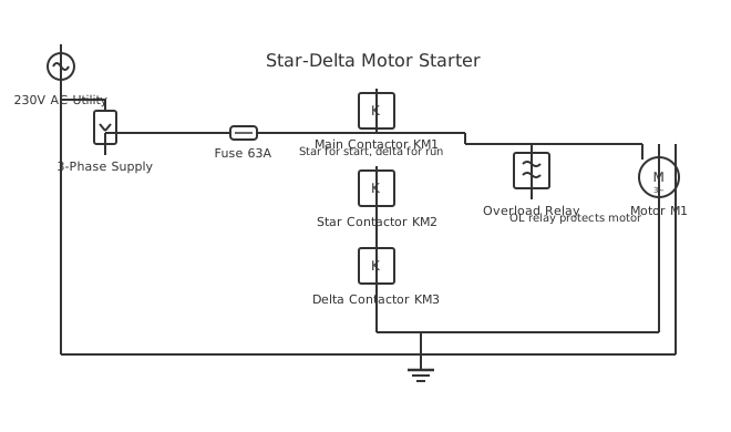
This is a free printable star delta starter diagram control circuit: download the diagram as SVG or open it and print to paper or PDF.
Star-delta starters reduce inrush current during three-phase motor startup by initially connecting windings in star configuration.
Diagram checks and scope
- Components
- 9
- Wired connections
- 11
- Automated check
- Automated pin, route, source, and topology checks passed; this is not a safety certification.
Three-phase motors connected directly to full voltage draw inrush currents of 6-10 times normal, causing voltage dips affecting equipment. Star-delta starting reduces inrush to 2-3 times by temporarily connecting motor windings in star configuration, reducing initial winding voltage to approximately 57% of line voltage. This reduces inrush while allowing acceleration to 75-80% of synchronous speed. A timer circuit then switches from star to delta configuration as the motor accelerates, applying full voltage for rated torque. The control circuit uses a start pushbutton energizing a contactor that closes main contacts. Simultaneously, a star-point contactor closes, connecting motor phases together. A timer relay initiates countdown. When the timer expires (5-10 seconds), it energizes a delta contactor switching the configuration while de-energizing the star contactor. Overload protection monitors motor current and trips if it exceeds safe levels. A stop pushbutton de-energizes all contactors. The control circuit operates at reduced voltage (120V or 240V) independent of the three-phase power level.
How to wire star delta starter diagram control circuit
- Identify the three-phase power source voltage (380V-480V) and auxiliary control power availability (120V-240V AC)
- Mount three main contactors in an enclosure: one for three-phase power, one for star, one for delta
- Wire the main power lines to the triple-throw contactor ensuring all three phases connect identically
- Connect the star point (connection of all three motor windings) to the star-point terminal through the star contactor
- Install a timer relay energized by the main contactor that de-energizes the star contactor and energizes the delta contactor after the preset time
Frequently asked questions
Why is star-delta starting necessary for three-phase motors?
Direct-on-line starting causes inrush currents of 6-10 times normal, causing voltage dips. Star-delta reduces inrush to 2-3 times normal current.
What determines the switch timing from star to delta configuration?
A timer relay measures elapsed time from contactor closure. Timing is typically adjustable from 2-20 seconds based on motor acceleration characteristics.
What happens if the star contactor fails to open during delta switching?
The neutral point remains shorted, causing severe phase voltage imbalance and excessive current triggering overload protection, preventing motor operation.
Can star-delta starters be used with variable frequency drives?
No. VFDs inherently limit inrush current by gradually ramping frequency, eliminating the need for star-delta starting.
What size motors require star-delta starting?
Generally, motors larger than 5.5 kW (7.5 horsepower) benefit from star-delta starting. Smaller motors can use direct-on-line without significant voltage impact.
Sources and verification
Review status: Not independently reviewed. Automated topology checks confirm stored terminals and routes, not the correctness of manufacturer pin assignments, ratings, regional codes, or installation decisions. Verify those claims against the current primary documentation before use.
- IEC 61082-1:2014 — Rules for electrotechnical documents — International Electrotechnical Commission. Supports: General diagram, drawing, table, and reference-designation presentation conventions. Checked 2026-07-15.
Related diagrams
- automatic star delta starter control circuit diagram
- control circuit of star delta starter
- star delta starter control circuit diagram with timer
- control wiring of star delta starter
- star delta control circuit diagram
- star delta starter circuit diagram