VFD (1-phase in, 3-phase out) Symbol
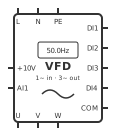
Definition: The single-phase input VFD symbol represents a variable frequency drive that takes a 200–240 V single-phase supply on L/N (plus PE) and produces a variable-frequency three-phase output on U/V/W to run a three-phase induction motor, with control terminals for digital run commands (DI1–DI4), a control common (COM) and an analog speed reference (AI1 with a +10V supply for a potentiometer).
Also known as: single-phase input VFD, 1-phase to 3-phase VFD, 220 V VFD, single-phase inverter, AC drive, frequency inverter, variable speed drive, phase converter VFD.
What the VFD (1-phase in, 3-phase out) symbol means
The power side has three groups. L and N are the single-phase mains input (L/N), PE is the protective earth for both the drive and the motor, and U/V/W are the three-phase motor output. The drive rectifies the single-phase input onto a DC bus and inverts it to a three-phase output whose voltage tops out near the supply voltage, so a 230 V input drive runs a motor connected for 230 V — for a common 230 V Δ / 400 V Y motor that means wiring the motor terminal box in delta.
The control side is low voltage. DI1 is run forward and DI2 is run reverse in this symbol's default assignment; DI3 and DI4 select preset (multi-speed) frequencies or act as fault reset, depending on parameters. COM is the common return for the digital inputs and the analog circuit. +10V is a reference output for a speed potentiometer, and AI1 is the 0–10 V speed reference input. The drive only follows these terminals once its parameters select terminal run commands and AI1 as the frequency source; many drives ship set to keypad control.
How to identify the VFD (1-phase in, 3-phase out) symbol
Look for a rectangle labelled VFD or inverter with a two-wire L/N supply entering one edge, a three-wire U/V/W output to a motor symbol on the opposite edge, and a row of small control terminals (DI1–DI4, COM, +10V, AI1). A three-phase input drive symbol instead shows L1/L2/L3 on the input. The single-phase drive is often the cheapest way to run a three-phase motor from a domestic or workshop supply.
Terminal names vary by maker: X1–X4 or S1–S4 for digital inputs, GND or DCM for COM, AVI or VI for AI1, and R/S or L1/L2 for the supply. Map this symbol's logical terminals to the exact drive's manual before wiring.
Live editor identity: Live-library identity: `vfd-1ph-in`, 100 × 120 canvas units, 13 logical terminals. Match this exact SVG and terminal list when identifying the placeable editor symbol; do not identify a physical package from the schematic outline alone.
Function and usage boundary
The drive varies output frequency and voltage together (V/f or sensorless vector control) to set motor speed, ramps it up and down to avoid inrush, and provides electronic motor overload protection set from the motor's nameplate current. Direction is reversed electronically, so no reversing contactors are needed.
Typical wiring: supply L/N through the fuses or MCB size the manual specifies and connect PE to the drive and the motor frame. Run U/V/W to the motor, ideally in screened cable earthed at both ends. For local control wire a run switch from DI1 to COM (run forward) and a second switch from DI2 to COM (reverse); with NPN-style inputs closing a contact between DIx and COM starts the drive. For manual speed control fit a 1–10 kΩ potentiometer with its ends on +10V and COM and its wiper on AI1. A PLC can replace the switches with relay outputs on DI1/DI2 and an analog output on AI1.
Usage boundary: Use the VFD (1-phase in, 3-phase out) abstraction only when the intended circuit can be expressed through these logical ports: `l` (L (single-phase line in)), `n` (N (neutral in)), `pe` (Protective earth), `u` (U (motor output)), `v` (V (motor output)), `w` (W (motor output)), `di1` (Digital input 1 (run forward)), `di2` (Digital input 2 (run reverse)), `di3` (Digital input 3 (multi-speed)), `di4` (Digital input 4 (multi-speed / reset)), `com` (COM / GND (control common)), `p10v` (+10 V potentiometer reference), `ai1` (Analog input 1 (0–10 V speed reference)). Select a versioned physical profile and exact manufacturer datasheet before assigning package pins, ratings, or fabrication dimensions.
Logical terminals
The live editor exposes `l` (L (single-phase line in)), `n` (N (neutral in)), `pe` (Protective earth), `u` (U (motor output)), `v` (V (motor output)), `w` (W (motor output)), `di1` (Digital input 1 (run forward)), `di2` (Digital input 2 (run reverse)), `di3` (Digital input 3 (multi-speed)), `di4` (Digital input 4 (multi-speed / reset)), `com` (COM / GND (control common)), `p10v` (+10 V potentiometer reference), `ai1` (Analog input 1 (0–10 V speed reference)). These are stable logical terminal IDs for diagram connectivity, not a promise that they equal physical package pin numbers.
| Logical ID | Editor terminal name |
|---|---|
| l | L (single-phase line in) |
| n | N (neutral in) |
| pe | Protective earth |
| u | U (motor output) |
| v | V (motor output) |
| w | W (motor output) |
| di1 | Digital input 1 (run forward) |
| di2 | Digital input 2 (run reverse) |
| di3 | Digital input 3 (multi-speed) |
| di4 | Digital input 4 (multi-speed / reset) |
| com | COM / GND (control common) |
| p10v | +10 V potentiometer reference |
| ai1 | Analog input 1 (0–10 V speed reference) |
Polarity and direction
Polarity or supply meaning is encoded on `pe` = Protective earth, `com` = COM / GND (control common). Do not reverse these logical connections, and verify the physical package pin number in the exact device datasheet.
Reference designator
Project-defined: No single reference letter is asserted for this broad symbol. Apply the project standard and equipment-classification rules consistently.
Where the VFD (1-phase in, 3-phase out) symbol is used
- Running three-phase motors on lathes, mills, drill presses and saws from a single-phase workshop supply
- Pumps, fans and blowers that need speed control or soft starting on a 230 V supply
- Small conveyors and mixers controlled by a PLC through digital inputs and a 0–10 V speed reference
- Replacing capacitor-start single-phase motors with a three-phase motor and a drive for smoother speed control
- Training rigs demonstrating VFD terminal control, preset speeds and potentiometer speed adjustment
Key facts
- Never connect mains to U/V/W: the motor output terminals are only for the motor, and feeding them with mains destroys the drive.
- A 230 V single-phase input drive gives a three-phase output of about 230 V, so a 230/400 V motor must be connected in delta.
- Start and stop the motor from DI1/DI2, not by switching the supply; frequent mains switching stresses the drive's DC-bus charging circuit.
- Do not open a contactor or isolator between the drive and the motor while the drive is running unless the drive is designed for it.
- A speed potentiometer connects ends to +10V and COM and the wiper to AI1; reversing the ends reverses the speed direction of the knob.
- The DC bus capacitors stay charged after power-off; wait for the time stated on the drive (often 5–10 minutes) and check before touching terminals.
- Drive leakage current can trip ordinary RCDs; use the RCD type and rating the manufacturer specifies and keep PE connected at all times.
Common interpretation mistakes
- Treating the VFD (1-phase in, 3-phase out) drawing (100 × 120 canvas units) as a physical footprint. The schematic outline expresses electrical intent; package and panel dimensions come from the selected physical profile.
- Copying `l`, `n`, `pe`, `u`, `v`, `w`, `di1`, `di2`, `di3`, `di4`, `com`, `p10v`, `ai1` directly to a wire marker or manufacturer package pin number. These are logical VFD (1-phase in, 3-phase out) port IDs and require an exact ordered-part terminal map.
- Reversing a polarity-marked VFD (1-phase in, 3-phase out) terminal because the symbol was rotated or mirrored on the sheet.
Frequently asked questions
Can a single-phase input VFD run a three-phase motor?
Yes, that is its purpose. The drive converts 230 V single-phase to a variable-frequency three-phase output on U/V/W. The motor must be rated for about 230 V between phases (a 230/400 V motor connected in delta), and the drive must be rated for the motor's full-load current.
How do I wire a potentiometer to the VFD for speed control?
Connect the two outer potentiometer pins to +10V and COM and the middle wiper pin to AI1, then set the drive's frequency source to AI1. A 1–10 kΩ linear potentiometer is typical. If the speed goes down when you turn it clockwise, swap the two outer wires.
How do DI1 and DI2 start the drive?
With terminal control selected, closing a contact between DI1 and COM runs the motor forward and between DI2 and COM runs it in reverse; opening the contact stops it on the programmed ramp. Use dry contacts, a selector switch or PLC relay outputs. Some drives also support PNP wiring selected by a jumper or switch.
Can I put a contactor on the VFD output to the motor?
Avoid switching a contactor between the drive and the motor while the drive is running; breaking the output under load can trip or damage the drive. Use the drive's run inputs to stop the motor. Where a contactor is required for isolation, interlock it so it only switches when the drive output is off.
Why does my VFD ignore the terminal switches?
Most drives ship set to keypad control. Change the run-command source parameter to terminals and the frequency source to AI1 (or a preset speed), and check that the input mode matches your wiring (NPN inputs switched to COM versus PNP inputs switched to +24 V).
Does a VFD replace motor overload protection?
Usually yes for a single motor: the drive's electronic thermal overload protects the motor once its current parameter is set to the motor nameplate full-load current. You still need short-circuit protection on the drive's supply (fuses or MCB as specified), and a separate overload relay or thermistor relay if the drive feeds more than one motor.
Sources and verification
- IEC 60617:2026 DB — Graphical symbols for diagrams (International Electrotechnical Commission) — The current official IEC graphical-symbol database and the electrotechnical areas it covers. Exact symbol identity data requires IEC access.; claim scope: standards
- IEEE/ANSI 315-1975 — Graphic Symbols for Electrical and Electronics Diagrams (IEEE Standards Association) — The official catalogue record for North American diagram symbols and reference-designation letters; IEEE lists the standard as inactive-reserved.; claim scope: standards, reference_designator
- IEC 61666:2010+AMD1:2021 — Identification of terminals within a system (International Electrotechnical Commission) — General principles for identifying terminals within systems; it does not replace the exact ordered-device datasheet.
- IEC 81346-2:2019 — Object classes and reference-designation codes (International Electrotechnical Commission) — The official classification scheme used to form reference designations across technical disciplines.; claim scope: reference_designator
- IEC 61082-1:2014 — Preparation of documents used in electrotechnology (International Electrotechnical Commission) — General presentation rules for electrotechnical diagrams, drawings, and tables.; claim scope: standards, usage
Geometry fingerprint: 558396aa5ce0d722. A changed SVG, canvas size, or terminal definition invalidates the recorded review.
Related symbols
- Line Reactor symbol
- Circuit Breaker (MCB) symbol
- 3-Phase Motor symbol
- Push Button NO symbol
- Compact PLC (FX3U / LX3V style, AC powered) symbol
- Potentiometer symbol
- Selector Switch 2-Position symbol
- VFD / Variable Frequency Drive symbol
Physical components that use this symbol
A schematic symbol defines electrical intent; the physical profile adds package or panel dimensions and mounting data.
Place the VFD (1-phase in, 3-phase out) symbol directly on a wiring diagram or schematic in the free online editor — no download required.