Stove Wiring Diagram — Free & Editable
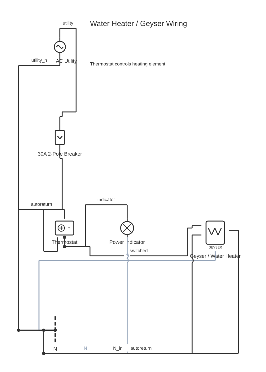
This is a free printable stove wiring diagram: download the diagram as SVG or open it and print to paper or PDF.

This Stove wiring diagram shows 6 components and 11 routed connections, including 1 × Supply (AC voltage source), 1 × Q1 (Breaker), 1 × Q2 (Switch Dpst), 1 × E1 (Cooker) and 1 × E2 (Cooker). Use it to inspect the shown topology, then confirm ratings and terminal assignments against the equipment documentation for your installation.
Diagram checks and scope
- Components
- 6
- Wired connections
- 11
- Automated check
- Automated pin, route, source, and topology checks passed; this is not a safety certification.
What this Stove Wiring Diagram drawing contains. The rendered example uses 1 × Supply (AC voltage source), 1 × Q1 (Breaker), 1 × Q2 (Switch Dpst), 1 × E1 (Cooker), 1 × E2 (Cooker) and 1 × PE (protective earth). Lighting drawings must keep the line, switched line, neutral and protective-earth functions unambiguous across every switching point. The component names in the list below come from the editable canvas, while the wire summary comes from the saved start and end terminals. This makes the written explanation auditable against the image instead of presenting an unrelated stock circuit.
Reading the stored graph from terminal to terminal gives this sequence: 1. Supply pos terminal connects to Q1 line terminal on the L net. 2. Q1 load terminal connects to Q2 in1 terminal. 3. Supply neg terminal connects to Q2 in2 terminal on the N net. 4. Q2 out1 terminal connects to E1 l1 terminal. 5. Q2 out1 terminal connects to E2 l1 terminal. 6. E1 l1 terminal connects to E1 l2 terminal. 7. E2 l1 terminal connects to E2 l2 terminal. 8. Q2 out2 terminal connects to E1 neutral terminal. 9. Q2 out2 terminal connects to E2 neutral terminal. 10. E1 earth terminal connects to PE gnd terminal on the PE net. 11. E2 earth terminal connects to PE gnd terminal. Its named nets are “L”, “N” and “PE”. A line joining two terminals records electrical continuity in this reference; visual proximity alone does not create a connection. Junctions, bridges and terminal labels therefore matter when the drawing is edited or exported.
Trace the live path through protection and the switching contacts to the luminaire, then follow the neutral return independently. Multiway arrangements use common and traveller terminals whose physical positions vary by device. In this particular graph, the first visible path is Supply pos terminal connects to Q1 line terminal on the L net., Q1 load terminal connects to Q2 in1 terminal., Supply neg terminal connects to Q2 in2 terminal on the N net. and Q2 out1 terminal connects to E1 l1 terminal.. Follow the remaining rows in the connection table before changing a symbol or moving a conductor, because a neat layout is not evidence that a terminal function is correct.
Confirm the supply system, switch terminal markings, lamp or driver compatibility, neutral availability and earthing requirements. Dimmers and electronic drivers also require an explicit load-type and minimum-load check. Automated validation checks that component IDs and terminal IDs exist, routes terminate on pins, the graph has a recognized source, and the saved topology has no blocking structural fault. It does not determine conductor size, protective-device rating, fault current, insulation class, environmental suitability or compliance with local rules. Those decisions require project values and the current primary documentation.
How to wire stove wiring diagram
- Read the Stove Wiring Diagram source path For this stove wiring diagram, begin at Supply (AC voltage source) and trace every stored terminal pair toward the load or output; do not infer continuity from lines that merely cross.
- Match every terminal name Compare the Stove Wiring Diagram terminal labels shown in the connection table with the current device or standard documentation before assigning real conductors.
- Set project-specific ratings Replace placeholder values in the stove wiring diagram with verified voltage, current, protection, conductor and environmental data for the actual installation.
- Run the electrical checks again After editing Q1 (Breaker) or any route, validate the graph and inspect every reported open terminal, source fault, collision and disconnected island.
- Release a controlled copy Export the revised Stove Wiring Diagram drawing only after a competent reviewer has compared it with the bill of materials, manufacturer documents and applicable rules.
Specifications
| Topic | Stove Wiring Diagram |
|---|---|
| Components shown | 6 |
| Routed connections | 11 |
| Named nets | L, N, PE |
| Verification scope | Stored pins, routes, source path and graph topology |
Safety warnings
- Prove the circuit dead with an appropriate method before touching fixed wiring.
- Keep neutral and protective earth separate except at the bonding point defined by the supply system and local rules.
Tools needed
- The current manufacturer datasheet, connector schedule or applicable standard for every real device
- A suitable meter and proving method for the voltage class being worked on
- The editor validation report and a controlled terminal or wire schedule
Common mistakes
- Treating the stove wiring diagram illustration as proof of a manufacturer pinout or conductor rating when those values are not encoded in the graph.
- Connecting by component position or wire colour instead of checking the named terminals in the Stove Wiring Diagram connection path.
- Using terminal position or wire colour to identify common and traveller conductors instead of testing and reading the device markings.
Troubleshooting
- The Stove Wiring Diagram path appears open
- Cause: A route ends on the wrong pin, a terminal was renamed, or a required return path is absent. Fix: Trace the connection rows in order, restore the documented terminal mapping, and run validation again.
- The edited drawing passes visually but validation fails
- Cause: A conductor may stop off-pin, cross a component body, create a source short or leave a disconnected island. Fix: Open each blocking finding, correct the referenced component or route, then re-run the topology check before export.
- The real equipment behaves differently
- Cause: The stored reference does not match the exact model, revision, supply or contact state. Fix: De-energize safely, return to the current primary documentation, and revise the symbol terminals and values before further testing.
Frequently asked questions
What exactly is verified on this stove wiring diagram?
The saved Stove Wiring Diagram graph is checked for known components and terminals, pin-snapped routes, a recognizable source path and blocking topology defects. Exact equipment ratings and manufacturer assignments are outside that automated scope.
Which components are actually shown in this Stove Wiring Diagram diagram?
The current editable graph contains 1 × Supply (AC voltage source), 1 × Q1 (Breaker), 1 × Q2 (Switch Dpst), 1 × E1 (Cooker), 1 × E2 (Cooker) and 1 × PE (protective earth). The bill of materials on this page is derived from those saved symbols rather than a generic shopping list.
How are the stove wiring diagram connections documented?
The graph contains 11 terminal-to-terminal links. The first path shown is Supply pos terminal connects to Q1 line terminal on the L net.
Can I use the drawing as an installation instruction?
Use it as an editable reference and review aid. Verify the exact equipment documentation, ratings, protection, conductor selection and local requirements before construction or release.
Sources and verification
Review status: Not independently reviewed. Automated topology checks confirm stored terminals and routes, not the correctness of manufacturer pin assignments, ratings, regional codes, or installation decisions. Verify those claims against the current primary documentation before use.
- IEC 61082-1:2014 — Rules for electrotechnical documents — International Electrotechnical Commission. Supports: General diagram, drawing, table, and reference-designation presentation conventions. Checked 2026-07-15.